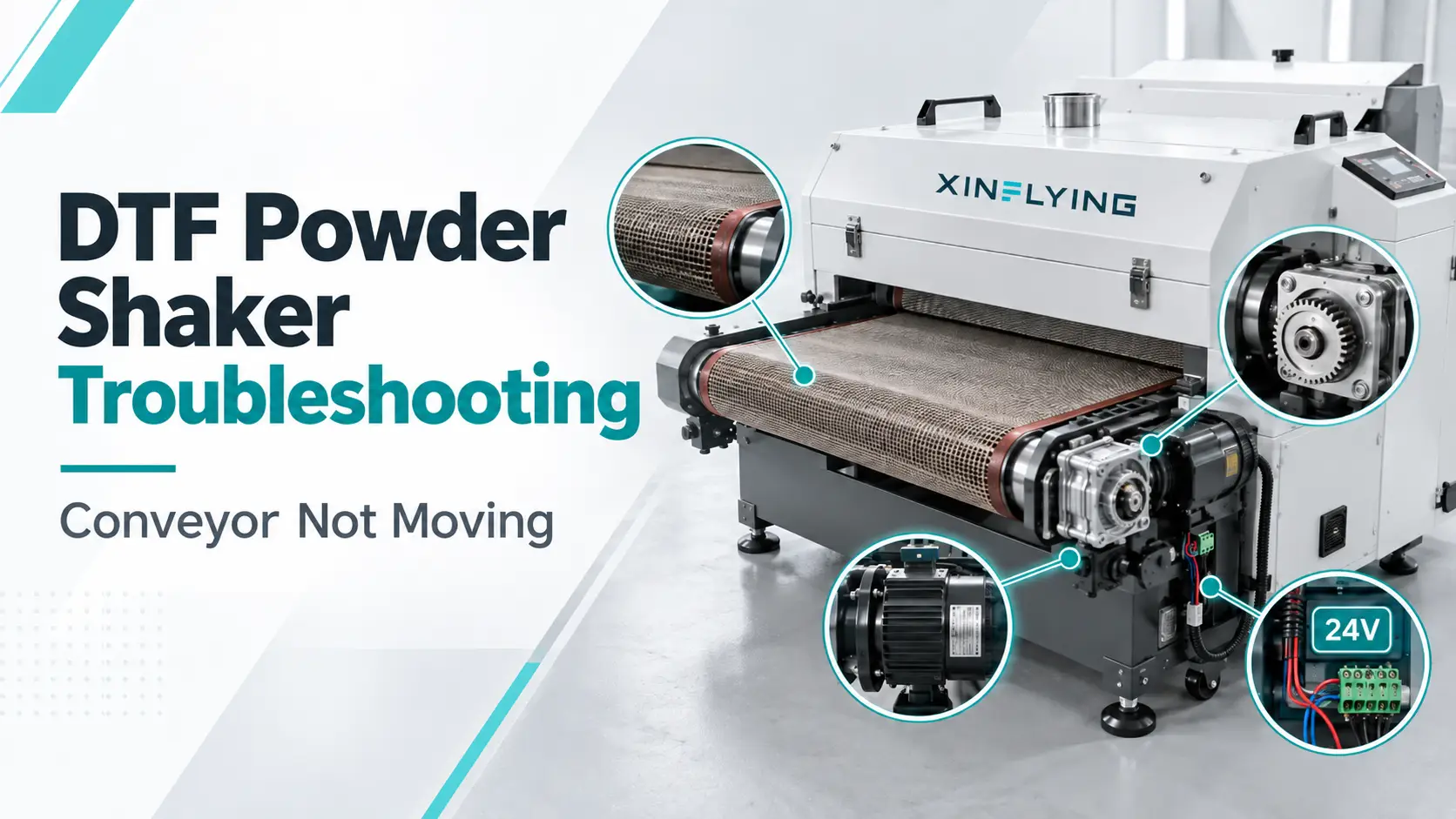
When a DTF powder shaker conveyor or mesh belt will not move in manual mode, first separate a mainboard output fault from a fault in the conveyor drive branch. On compatible touch-screen models, a technician can isolate the circuit by exchanging the conveyor and powder-dusting output connections. The next checks are the drive gear, DC 24 V motor input, wiring, and motor.
This DTF powder shaker troubleshooting procedure is based on a real service workflow for a touch-screen powder shaking machine. It applies specifically to the documented configuration. Connector assignments, motor voltage, control logic, and safety interlocks can differ between models, so confirm the wiring diagram and service instructions for the exact machine before testing.
Quick Diagnosis: What Each Test Result Means
| Test result | Most likely diagnostic direction |
|---|---|
| Conveyor does not respond in manual mode, but powder dusting still works | The fault is likely in the conveyor output channel, conveyor harness, drive gear, or conveyor motor |
| After the approved output-port exchange, the conveyor moves but the powder function stops | The fault points to the original conveyor output channel on the mainboard |
| After the approved output-port exchange, the conveyor still does not move | Inspect the conveyor drive gear, gear screw, motor, and conveyor wiring |
| The gear is secure and the motor receives the specified DC 24 V, but the motor does not run | The conveyor motor is the primary suspect |
| The motor does not receive DC 24 V, but the mainboard output does | Inspect the cable, terminals, and connectors between the mainboard and motor |
| Neither the motor input nor the commanded mainboard output reaches the specified voltage | Confirm the command state and model-specific interlocks, then diagnose the mainboard output circuit |
Do not replace the motor or mainboard from one symptom alone. A correct diagnosis depends on whether the fault stays with an output channel or stays with the conveyor branch.
Before Troubleshooting the DTF Powder Shaker Conveyor
A powder shaker combines electrical power, moving rollers, gears, hot surfaces, and fine hot-melt powder. Separate operator-level observations from technician-level electrical work.
An operator can safely record the fault, confirm which function has stopped, and inspect accessible areas after the approved shutdown. Removing electrical covers, exchanging mainboard connections, and taking live-voltage measurements should be handled by a qualified technician using the machine’s service information.
Before opening the machine:
- Stop the print job and remove film only through the approved unloading procedure.
- Turn off and isolate the machine from power.
- Allow the dryer and heated sections to cool.
- Keep hands, tools, clothing, and cables away from rollers and gears.
- Follow the safety data sheet for the hot-melt powder. Do not blow powder into the air with compressed air.
- Photograph the original connector positions before disconnecting anything.
- Confirm the connector labels, pinout, voltage, and output compatibility for the exact model.
Never exchange connectors while the machine is energized. Never bypass a fuse, sensor, thermal protector, guard switch, or other interlock to make the conveyor run.
Step 1: Confirm That the Conveyor Is the Failed Function
Use the touch screen’s manual controls to identify the affected function before removing a cover. A useful fault description is more specific than “the powder shaker does not work.”
Record the following:
- Does the conveyor or mesh belt respond to the manual conveyor command?
- Does the powder-dusting function still run?
- Does the motor remain completely silent, hum, click, or try to move?
- Does the belt move briefly and stop, or does it never start?
- Is there an alarm, abnormal display state, burning smell, or tripped protective device?
- Did the fault appear after cleaning, transport, a media jam, wiring work, or a sudden stop?
Power the machine down before checking for an obvious mechanical obstruction. Look for folded film, compacted powder, a foreign object, or another condition preventing the conveyor mechanism from moving. Do not use the motor to force a jammed belt or roller.
If the conveyor works but the powder-dusting or shaking motor does not, this is a different fault path. Use the separate guide for an A2 DTF powder shaker motor that is not working rather than applying the conveyor diagnosis to the wrong motor.
Step 2: Isolate the Mainboard Output With the Port-Exchange Test
The documented touch-screen powder shaker uses two relevant mainboard connections:
- the conveyor or mesh-belt output port; and
- the powder-dusting output port.
The service procedure exchanges the two wire connections to determine whether the failure belongs to the mainboard output channel or the conveyor branch. Perform this test only when the manufacturer confirms that the two outputs and connectors are compatible for the exact machine.
How a technician should perform the test
- Shut down and isolate power.
- Identify the conveyor output and powder-dusting output from the wiring diagram and board labels.
- Take a clear photo of both original connections.
- Label each harness so it can be returned to its original port.
- Inspect both plugs for a loose terminal, discoloration, powder contamination, or damaged locking tabs.
- Exchange the two approved wire connections exactly as described in the model’s service procedure.
- Reinstall any cover or guard required for a safe functional test.
- Clear personnel and tools from all moving parts.
- Restore power and command the functions one at a time while observing the conveyor and powder mechanism.
- Record which mechanism moves and which does not.
- Isolate power again and restore both connectors to their original positions before continuing with repair work.
How to interpret the result
If the conveyor moves and the powder function does not move after the exchange: the failure has followed the original conveyor output channel. The supplied service procedure identifies the mainboard output port as the problem and directs mainboard replacement. Before replacing the board, confirm the result is repeatable, the ports were correctly identified, and no model-specific command or interlock explains the missing output.
If the conveyor still does not move after the exchange: the fault remains with the conveyor branch. Remove the appropriate side cover and inspect the conveyor motor gear, gear screw, wiring, and motor.
If the result is inconsistent or both functions behave abnormally: stop the test, restore the original connections, and verify the wiring diagram with technical support. Do not continue swapping connectors to search for a result.
This test is valuable because it changes one variable at a time. It prevents a technician from replacing a motor when the board channel is faulty, or replacing a mainboard when a loose drive gear is the actual cause.
Step 3: Remove the Side Cover and Check the Conveyor Drive Gear
If the conveyor still does not move during the approved port-exchange test, isolate power and remove the machine’s side cover using the documented screw locations. Keep the screws organized and do not operate the machine with required guards removed.
Inspect the conveyor motor and drive gear area for:
- a loose gear-retaining screw;
- a gear that has shifted on the motor shaft;
- poor engagement between the driving and driven parts;
- a cracked, badly worn, or damaged gear;
- a shaft that does not rotate freely under the approved manual inspection method;
- powder or debris interfering with the drive; and
- a loose motor mount or visibly misaligned drive.
The original service procedure specifically instructs the technician to check whether the gear screw is loose. A motor can run while a loose gear slips on its shaft, leaving the mesh belt stationary. In that condition, replacing the motor will not solve the problem.
If the screw is loose, reposition and secure the gear according to the model’s mechanical service specification. Do not guess the tightening torque or apply an unapproved thread-locking compound. Rotate or move the mechanism by hand only when the manual permits it and the machine has been verified de-energized.
After correcting a mechanical issue, reinstall the required cover and perform a short controlled test. If the gear is secure and the conveyor still does not move, continue to the motor-voltage check.
Step 4: Measure the Conveyor Motor Input Voltage
For the machine covered by the source procedure, the normal conveyor motor input is DC 24 V when the conveyor is commanded to run. This value is model-specific. Do not assume that every DTF powder shaker, shaker dryer, or conveyor motor uses 24 V.
Live-voltage measurement should be performed only by a qualified technician who has:
- the correct wiring diagram and connector pinout;
- an appropriate and verified multimeter;
- approved probes and personal protective equipment;
- a safe measurement reference; and
- a clear understanding of the command state required to energize the output.
The technician should measure at the conveyor motor input while the manual conveyor command is active. Avoid piercing insulation or shorting adjacent terminals. If the connector cannot be tested safely with approved probes, stop and use the manufacturer’s service method.
What the voltage result tells you
| Motor input result | Interpretation | Next action |
|---|---|---|
| Approximately DC 24 V is present, the gear is secure, and the motor does not run | The supply reaches the motor, so the motor or its local terminal is the primary suspect | Inspect the motor connector; replace the motor if the connection is sound and the service diagnosis confirms failure |
| No voltage is present | The fault is upstream of the motor | Inspect the harness and measure the commanded mainboard output using the approved procedure |
| Voltage is low, unstable, or disappears when the motor is commanded | There may be a poor connection, damaged cable, overloaded motor, supply problem, or failing output stage | Stop repeated testing and trace the circuit methodically |
| Correct voltage is present and the motor turns, but the belt does not move | Electrical drive is working | Return to the gear, coupling, shaft, and conveyor mechanism |
The supplied technical procedure states that when the input voltage is normal but the motor does not work, the motor should be replaced. That conclusion assumes the gear is correctly installed, the conveyor is not mechanically blocked, the connector is sound, and the measured voltage matches the model specification under the correct command condition.
Step 5: Trace the Cable Between the Motor and Mainboard
If the conveyor motor input is missing or abnormal, isolate power before inspecting or testing the harness. Follow the cable from the motor back to the mainboard without changing several connections at once.
Check for:
- a plug that is not fully seated;
- a terminal that has backed out of its connector housing;
- a cable pinched by the side cover;
- broken insulation or a conductor damaged by vibration;
- powder contamination inside a connector;
- corrosion, heat discoloration, or a burnt terminal; and
- a previous repair that changed the pin order.
Continuity and resistance checks must be made only on a de-energized circuit and according to the wiring diagram. Disconnect components as required by the service procedure so a parallel circuit does not create a misleading reading.
After the harness passes its inspection, a qualified technician can check whether the relevant mainboard output reaches the specified DC 24 V when the manual conveyor command is active.
- DC 24 V at the mainboard output but not at the motor: the cable, connector, or terminal between them is faulty.
- No specified output at the mainboard, with the command active: verify the display command, required interlocks, and port identification. If those are correct, the mainboard output channel is the primary suspect.
- The output-port exchange also caused the fault to follow the original conveyor port: this provides stronger evidence of a failed mainboard output channel.
Do not apply external 24 V power directly to the motor unless the manufacturer provides a specific bench-test procedure. Incorrect polarity, uncontrolled current, or an unexpected motor rating can damage the motor, board, or wiring and can create uncontrolled movement.
Reassemble and Validate the Repair
After the repair:
- Restore the conveyor and powder-dusting connectors to their original labeled ports.
- Confirm every terminal is locked and no wire is trapped by the cover.
- Reinstall the side cover, guards, seals, and all removed screws.
- Remove tools and loose hardware from the machine.
- Run a brief manual conveyor test with the area clear.
- Confirm smooth belt movement, normal sound, and reliable start and stop response.
- Test the powder-dusting function separately.
- Run a small controlled film test before returning to production.
Stop immediately if the conveyor stalls, the gear slips again, a connector becomes hot, a protective device trips, or there is grinding, smoke, or a burning smell.
Document the failed component, voltage readings, connector condition, and repair. This record is useful if the fault returns and helps technical support distinguish a recurring mechanical load from an electrical output problem.
Information to Send Technical Support
If the cause is still unclear, send:
- powder shaker model and serial number;
- a photo of the machine identification plate;
- a short video showing the manual conveyor command and the stationary belt;
- confirmation of whether powder dusting still works;
- photos of the conveyor and powder-dusting output labels;
- a photo of the conveyor motor label;
- the gear and retaining-screw condition;
- motor-input and mainboard-output readings, including the exact command state; and
- the result of the approved port-exchange test.
XINFLYING supplies different DTF printer system configurations, and their powder shaker controls are not necessarily interchangeable. For model-specific diagrams, test points, and replacement-part confirmation, contact XINFLYING technical support before replacing the mainboard or motor.
For a broader overview of printer-side faults, see the DTF printer troubleshooting guide.
Frequently Asked Questions
The most likely causes are a loose conveyor gear screw, a jammed drive, a failed 24 V conveyor motor, damaged wiring, or a missing mainboard output. Test in sequence: confirm the manual command, isolate the output channel, inspect the gear, measure the motor input, and then trace the cable and board output.
No. DC 24 V is the specified value in the service procedure used for this touch-screen powder shaker. Other machines can use different motors, supplies, connectors, or control methods. Always verify the motor label, wiring diagram, and manufacturer documentation for the exact model.
No. The powder-dusting or shaking motor moves powder, while the conveyor motor transports the film through the shaker. If the conveyor works but powder movement has stopped, follow the powder shaker motor troubleshooting procedure instead.