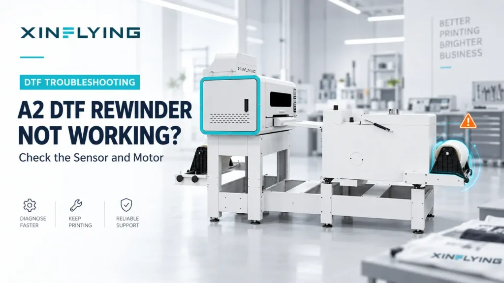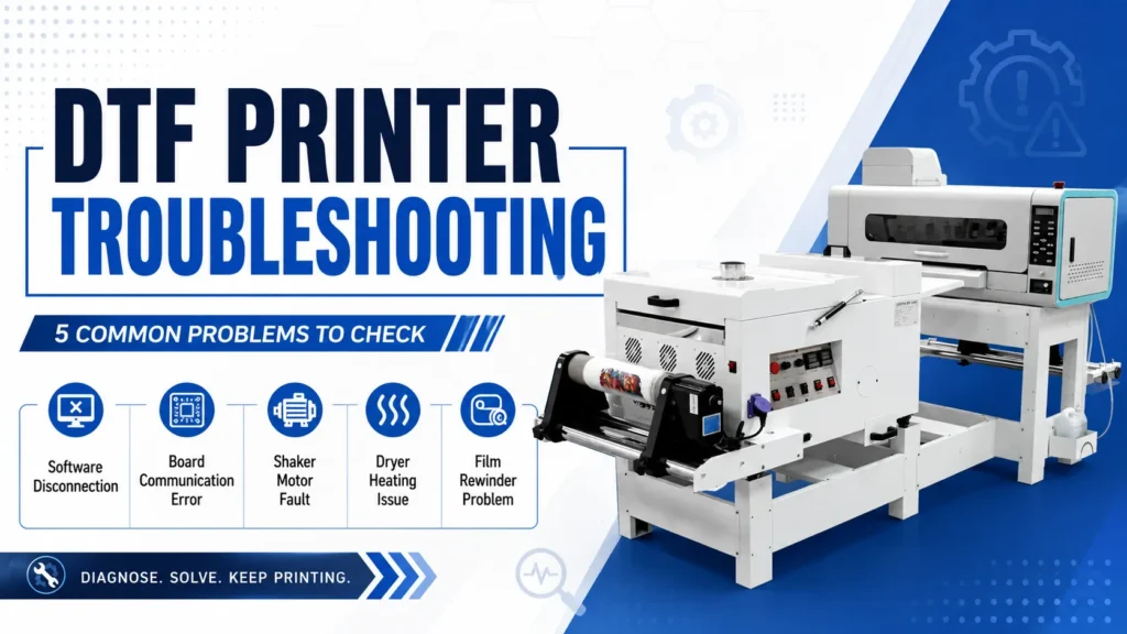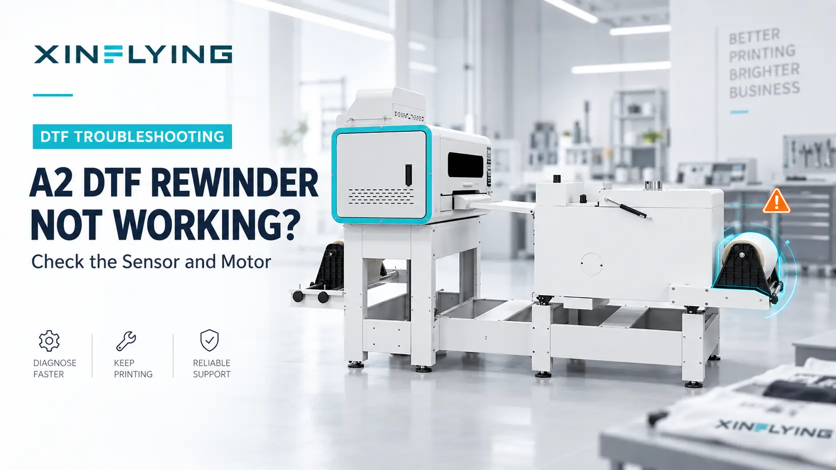
When the rewinder on a XINFLYING A2 does not take up film, first determine whether the motor is not turning or the shaft is turning without driving the core. Confirm correct film loading and core grip, then inspect the rewinder sensor, switch, and motor in that order. Stop the system before loose film reaches a hot dryer section, wraps around a roller, or pulls the print path out of alignment.
The XINFLYING A2 All-in-One Printer FAQ refers to this component as a paper rewinder and lists three checks: sensor, rewinder switch, and motor. In DTF production, the media is normally film. Do not apply the A2 sensor logic, motor values, or take-up settings to another model without confirmation.
Identify What “Not Working” Means
Observe the system without placing hands near moving parts.
| Symptom | Check first |
|---|---|
| Motor and shaft do not move | Sensor state, switch, motor command, and electrical path |
| Shaft turns but the core does not | Core holder, clutch, coupling, or core grip |
| Rewinder starts and stops at the wrong time | Sensor position, film loop, or sensor contamination |
| Roll builds to one side | Film alignment, roll position, and uneven tension |
| Motor stalls as the roll grows | Mechanical resistance, tension setting, coupling, or motor condition |
From a safe distance, record a short video that shows the film loop, sensor, shaft, and control switch while the fault occurs. Keep hands, clothing, and tools away from the moving film path.
Safety Before Inspection
Use the normal shutdown procedure and isolate power before touching the shaft, coupling, sensor wiring, switch, or motor. Allow the dryer to cool. If loose film creates an immediate entanglement or heat hazard, follow the model’s emergency-stop procedure. Do not pull film from a powered take-up system or bypass a sensor to make the motor run continuously.
1. Confirm Film Loading and Core Engagement
Before diagnosing electronics, verify the simple mechanical path:
- film is routed in the specified direction;
- the take-up core is installed squarely;
- holders or collars secure the core without side play;
- the film is attached straight across the core using the approved method; and
- there is enough initial wrap for the core to grip.
If the shaft rotates but the core does not, inspect the holder, coupling, or clutch specified for the model. Do not increase tension to compensate for a slipping core.
2. Check the Rewinder Sensor
The A2 FAQ lists the sensor first. Depending on the model, a take-up system may use a film loop, dancer position, or another sensing method to command the motor. Confirm the A2 sensor type and intended detection area in the service information. A blocked, misaligned, contaminated, or incorrectly triggered sensor can prevent the run command or cause incorrect cycling.
With power off, inspect the accessible sensor for:
- powder, dust, or film scraps on the sensing area;
- a loose bracket or changed angle;
- damaged cable or connector;
- film routed outside the intended detection area; and
- any documented dancer, trigger, or guide that cannot move freely.
Clean only with the approved method and follow the hot-melt powder safety data sheet (SDS). Do not use compressed air to blow powder from the sensor, and do not move the sensor without recording its original alignment.
After the sensor area is clean, reinstall all required covers and keep people and tools clear of the film path. When the official procedure allows a powered test, a trained technician can observe the documented sensor indicator or controller input while the film loop enters and leaves the detection area. Do not bypass the sensor to simulate a run command.
3. Verify the Rewinder Switch
Confirm that the rewinder is enabled in the correct operating mode. Inspect the switch for a broken actuator, loose mounting, or an abnormal feel. With power isolated, a technician can check its connector and wiring according to the electrical diagram.
If the switch has multiple directions or modes, record which selection fails. Do not assume the label or contact arrangement is identical across models.
4. Determine Whether the Motor Receives the Correct Command
If the film path, core, sensor, and switch are correct, the motor or its electrical supply becomes the next focus. A trained technician should use the model’s wiring diagram and rated values to determine whether the motor receives the expected command.
- Correct input with no motor movement points toward the motor, its local connection, or a mechanical lock.
- No input redirects diagnosis to the sensor, switch, wiring, controller output, or documented interlock.
- Movement without useful take-up points toward the coupling, clutch, shaft, or core holder.
The A2 FAQ does not provide a rewinder-motor voltage in this section, so do not reuse the powder-motor voltage or another model’s value. If the rated value, connector pinout, or command condition is not documented, contact XINFLYING support before testing.
5. Inspect Tension and Alignment Before Production
After reinstalling all guards and covers and removing tools from the film path, confirm that the rewinder does not pull the film sideways or create excessive tension. The roll should build evenly, the film loop should stay within the model’s intended range, and the printer should feed without visible skew.
Run a short controlled test and watch the full path from printer exit through the dryer to the take-up roll. Stop if the roll cones to one side, the film becomes tight between machines, or the motor repeatedly stalls.
Common Mistakes to Avoid
- Replacing the motor before checking whether the shaft or core turns.
- Bypassing the sensor instead of correcting film routing.
- Pulling film by hand while the system is energized.
- Increasing take-up force to correct a skewed roll.
- Using an unverified motor or controller from a different model.
- Changing sensor position without marking the original location.
Submit a Rewinder Inquiry
Send the model and serial number, a full-path video, sensor and switch photos, motor label, and a description of whether the shaft, core, or neither moves. Different XINFLYING DTF printer configurations may use different roll-handling systems. Send these details to XINFLYING to confirm the correct sensor, motor, and test procedure.