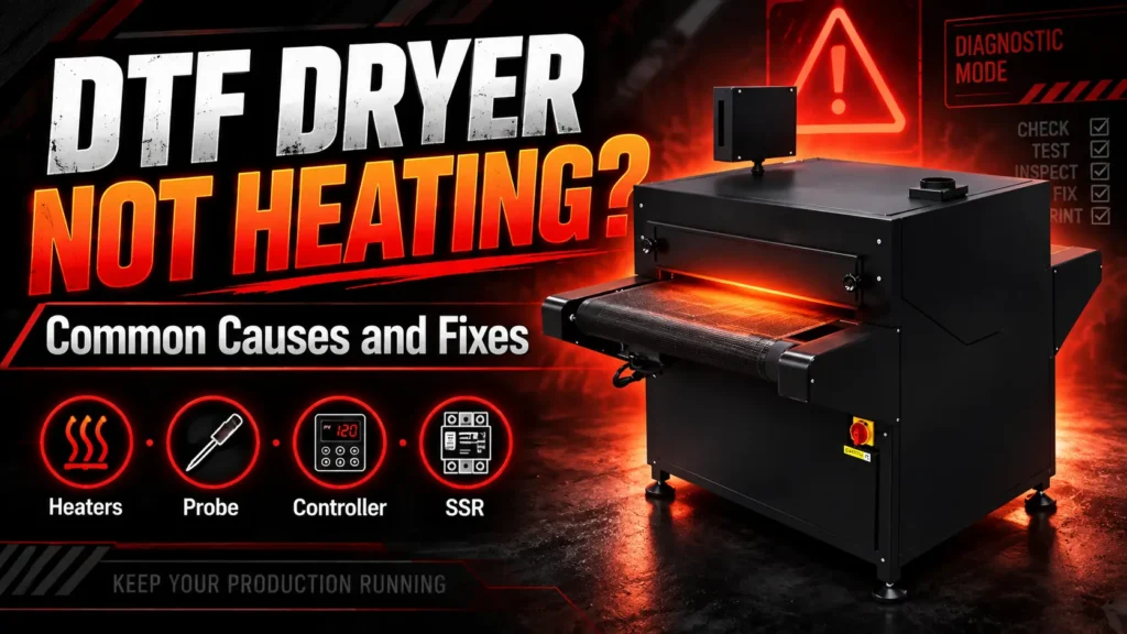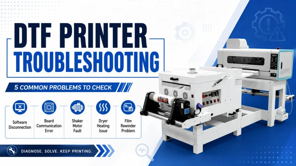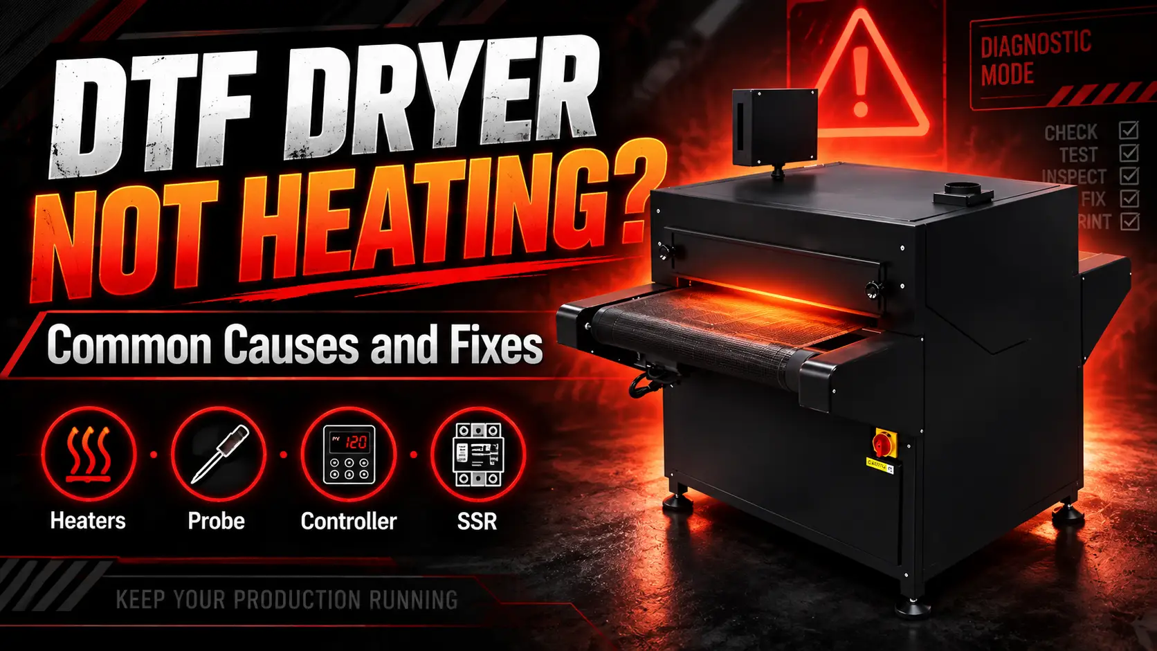
If your DTF dryer is not heating, first confirm whether every zone is cold or only one zone is affected. That distinction helps separate a settings or power-supply problem from an individual heater-circuit fault. The same first checks also apply when a DTF powder shaker and dryer produces little or uneven heat.
For the XINFLYING A2 All-in-One Printer, the troubleshooting sequence is to verify settings and power conditions, check individual heater zones, inspect the temperature probe and controller wiring, and then test the probe, temperature controller, and solid-state relay (SSR).
Dryers contain hot surfaces and potentially hazardous electrical energy. Operators should limit their checks to settings, visible status, alarms, and other noninvasive evidence. A qualified technician should perform all internal heater, relay, probe, and wiring tests using the electrical documentation for the exact model.
Define the Heating Symptom Before Testing
“Not heating” can describe several different failures:
| Symptom | Diagnostic direction |
|---|---|
| No heat anywhere | Power, heating command, controller, relay, wiring, or all heater circuits |
| One zone or side stays cool | Individual heater element, connection, or zone control |
| Displayed temperature never rises | Heater circuit, probe reading, or controller output |
| Displayed temperature is implausible | Probe, probe wiring, or controller input |
| Heat cycles unpredictably | Loose connection, probe position, controller, relay, or airflow/load condition |
Record the set temperature, displayed temperature, warm-up time, affected zone, alarms, and whether the film transport and powder-shaker functions operate normally. Do not judge heater operation by touching the oven or placing a hand near an opening.
Immediate Safety Steps
- Stop feeding printed film into the dryer.
- Use the normal shutdown procedure.
- Isolate power before opening any electrical cover.
- Allow hot components to cool fully.
- Keep flammable materials and loose powder away from hot sections.
If you smell burning insulation, see smoke, find a melted connector, or observe uncontrolled temperature rise, keep the unit off and request service. Do not reset it repeatedly.
Follow the safety data sheets (SDS) and ventilation requirements for the exact film and hot-melt powder in use. Do not continue heating material that produces unusual smoke, odor, or discoloration.
1. Confirm the Settings, Power Conditions, and Status
Before assuming a part has failed, verify that the heater function is enabled, the temperature unit and setpoint are correct, and the controller is not waiting for another documented operating condition. Record any alarm symbol or code.
Use the temperature and process settings approved for the exact film, powder, and equipment. This article does not provide a universal curing temperature because consumables and dryer designs differ.
If there is no heat in any zone, compare the machine nameplate with the installed power-supply specification. A technician should use the electrical documentation to verify the heater-circuit supply, fuse or breaker condition, and any documented airflow, transport, cover, or thermal interlock. Operators should not open an electrical panel or repeatedly reset a protective device.
2. Determine Whether All Heater Elements Work
The A2 FAQ lists the heater elements as the first hardware check. A multi-element dryer may produce some heat even when one element has failed, so “warm” does not prove that the entire heating system is operating.
A technician can compare zones using the test method approved for the model. Resistance and continuity tests require the heater circuit to be powered down, isolated, and verified de-energized. If the service procedure permits a powered zone-temperature comparison, restore every cover and safeguard first and use only the approved non-contact measuring method.
Record which zone fails and the identification shown on the heater or wiring diagram. Replacement parts must match the model’s electrical and thermal specifications.
3. Inspect the Temperature Probe and Controller Wiring
The A2 document next calls for checking poor contact at the probe and temperature-controller wiring. A loose, damaged, or contaminated connection can create a false temperature reading or prevent normal control.
With power isolated, a technician should check:
- connector seating and terminal tightness according to the service procedure;
- cuts, pinches, discoloration, or overheated insulation;
- probe cable routing away from damage points; and
- correct terminal identification before any wire is removed.
Label every conductor. Reversing or moving probe and control wiring can create unsafe readings.
4. Isolate the Probe, Controller, and Solid-State Relay
If heater elements and visible connections are confirmed, the A2 FAQ identifies three remaining candidates: the temperature probe, temperature controller, and solid-state relay (SSR).
Their roles are different:
- The probe reports temperature.
- The controller compares the reading with the setpoint and commands heat.
- The SSR switches power to the heater when commanded.
A technician must determine whether the probe reading is credible, whether the controller sends the expected heating command, and whether the relay output changes as specified in both the heater-on and heater-off states. If the service procedure permits component substitution, use one verified, compatible, known-good component at a time.
Do not bypass the probe, controller, relay, fuse, or thermal protection. A bypass can remove temperature control or safety protection and create fire or burn hazards.
5. Verify the Repair With a Controlled Warm-Up
After all covers and safeguards are restored, begin with an empty, monitored warm-up according to the model instructions. Confirm that:
- the displayed temperature rises plausibly;
- each zone warms as expected;
- temperature stabilizes rather than continuing to climb;
- there is no abnormal odor, smoke, unusual sound, or visible sign of overheating; and
- the unit shuts the heater off when commanded.
Only then run a small production test and evaluate curing under the approved process settings.
Submit a Dryer Heating Inquiry
To help the support team identify the correct circuit and next test, send:
- the equipment model and serial number;
- the power specification shown on the nameplate;
- a video of the controller display during warm-up;
- any alarm symbols or codes;
- the affected heating zone; and
- observations and test results recorded by the technician.
Avoid sending only a conclusion such as “the SSR is bad.” Include the readings or observations behind it.
Different XINFLYING DTF printer configurations may use different dryer circuits, sensors, and protection devices. If heating remains abnormal, contact XINFLYING Support or send the diagnostic information to XINFLYING. The team can use the exact model and recorded evidence to confirm the correct wiring diagram, component compatibility, and next diagnostic step.