Replace and Debug Printhead

Select Your Printer Model
(Default: Universal)
Choose your model from the drop-down menu below.

XINFLYING Replace and Debug Printhead

Applicable Model: Universal

Video Tutorial

Replace the printhead and its ribbon cables, restore the damper connections, and correct mechanical alignment using a printed test pattern.

Applicable model: General. Required items: compatible printhead and ribbon cables, screwdriver, dust-free cloth, acetate cloth tape, and printer control software.

Step 1. Remove the Old Printhead

1.1 Switch off and unplug the printer. Remove the carriage cover to expose the printhead assembly (See Figure 1.1, left).

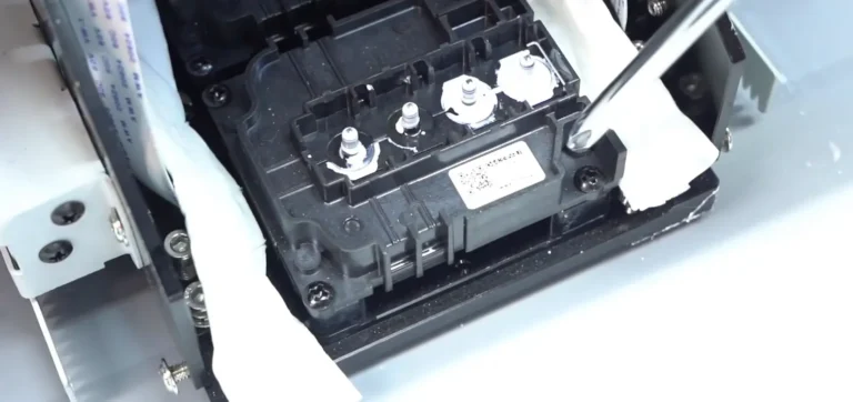
1.2 Place dust-free cloth on both sides of the printhead to catch ink. Lift off the dampers, keeping their ink tubes connected and their positions identified (See Figure 1.1, right).

Remove the carriage cover.
Protect the printhead area.

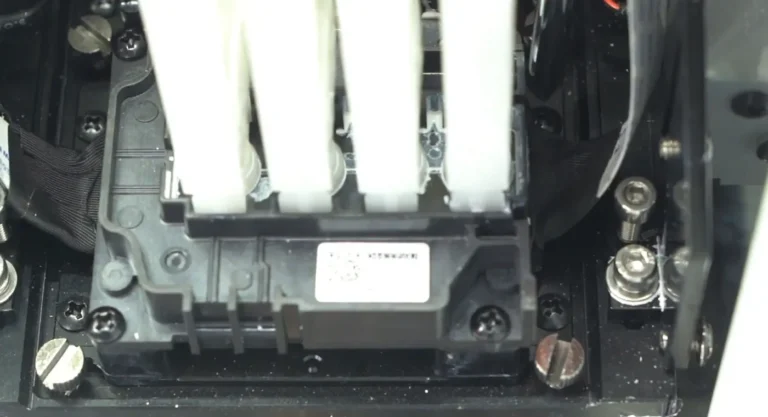
1.3 Remove the four printhead fixing screws. Lift the old printhead enough to access its cable connections, supporting it without straining the cables (See Figure 1.2, left).

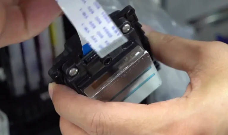
1.4 Remove the tape securing the ribbon cable connections, then pull the cables straight from their sockets. Retain the cable labels as connection references (See Figure 1.2, right).

Release the printhead fixing screws.
Disconnect the ribbon cables.

Step 2. Connect and Install the New Printhead

2.1 Inspect the replacement ribbon cables for oxidation or damage. Use compatible, undamaged cables; defective cables can damage the printhead or headboard.

2.2 Connect the labeled ribbon cables to the corresponding sockets on the new printhead. Match each label to its position, such as left upper to left upper and right lower to right lower. Align the exposed cable contacts with the socket contacts (See Figure 2.1, left).

2.3 Secure the cable connections with acetate cloth tape as shown, without pulling the cables out of position (See Figure 2.1, right).

Seat the labeled ribbon cable.
Secure the connection with tape.
Secure the connection with tape. 10:45

2.4 Handle the new printhead by its body without touching the nozzle surface. Place it in the original mounting position and reinstall the four fixing screws.

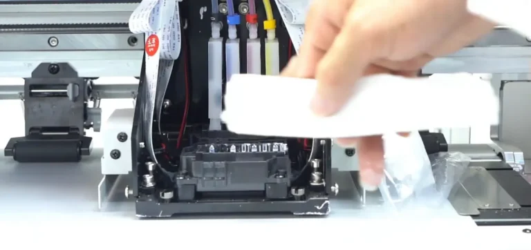
2.5 Keep dust-free cloth around the printhead while reinstalling the dampers in their original positions. Fully seat each damper, then remove the protective cloth and check the cable connections (See Figure 2.2).

Refit the dampers while protecting the surrounding area from ink.

Step 3. Check and Correct the Printhead Alignment

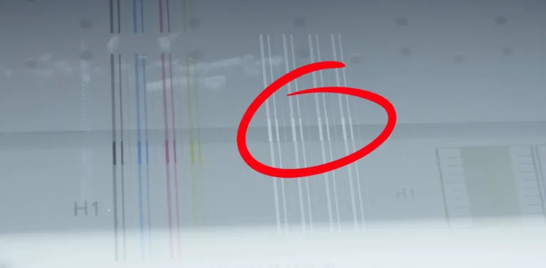
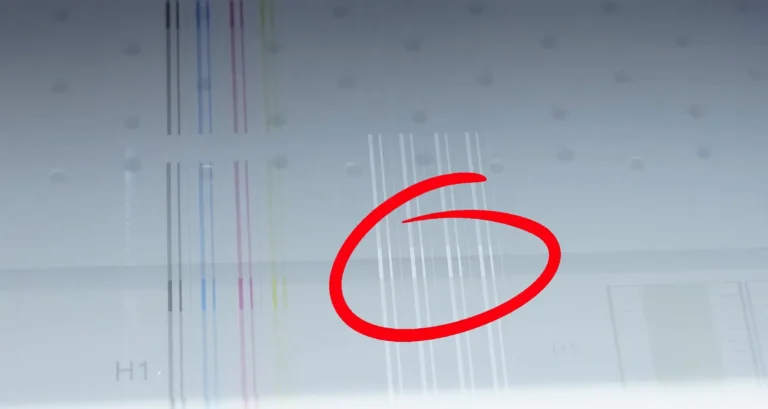
3.1 Clear the work area and power on the printer. Click Check in the printer control software to print a test pattern. Inspect the lines for visible offset or misalignment (See Figure 3.1, left).

3.2 Switch off and unplug the printer before adjustment. Loosen the four printhead fixing screws without removing them (See Figure 3.1, right).

Identify misaligned lines in the test pattern.
Loosen the fixing screws.

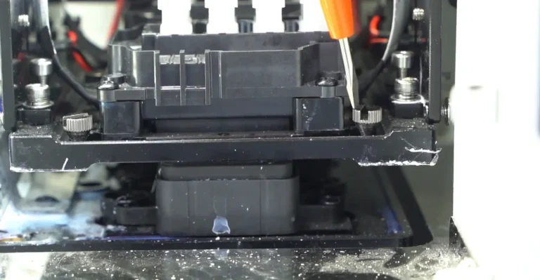
3.3 Use the two adjustment screws on the illustrated mount to correct the printhead vertical alignment. Adjust a small amount according to the printed deviation (See Figure 3.2).

Adjust the screws on both sides of the printhead mount.

3.4 Tighten the two fixing screws at opposite corners to hold the printhead for the next test (See Figure 3.3).

Secure two opposite corners before printing the next test.

Step 4. Retest and Finish the Installation

4.1 Power on the printer and click Check again to print the test pattern. Compare the lines with the previous result. If misalignment remains, switch off and unplug the printer before repeating the adjustment (See Figure 4.1, left).

4.2 Once the printed lines align correctly, switch off and unplug the printer. Tighten all printhead fixing screws to secure the final position (See Figure 4.1, right).

Check the corrected test pattern.
Tighten all fixing screws.

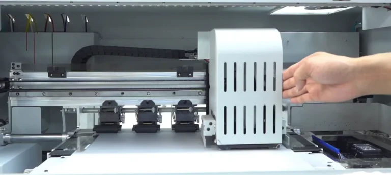
4.3 Refit and secure the carriage cover, keeping the cables and ink tubes clear of its edges (See Figure 4.2).

Refit the carriage cover after completing the alignment.

If you are not sure about any step, please contact the XINFLYING Technical Support Team for assistance.

© 2026 XINFLYING Technical Team. All rights reserved.
Do not reproduce or modify this document without permission.
For support, please contact: [email protected] | www.xin-flying.com

Request an Equipment Quote

Tell us your equipment and production needs. Our team will recommend a suitable machine and provide a tailored quotation.