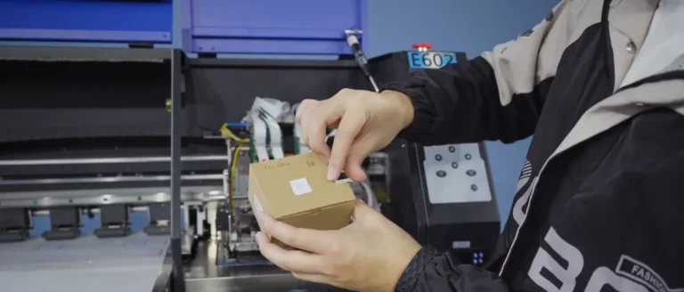
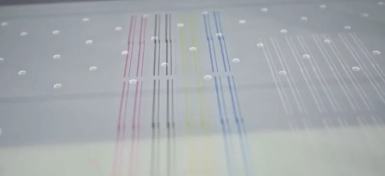
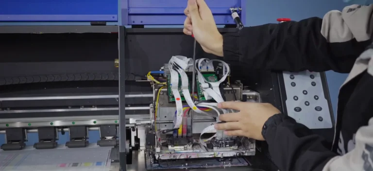
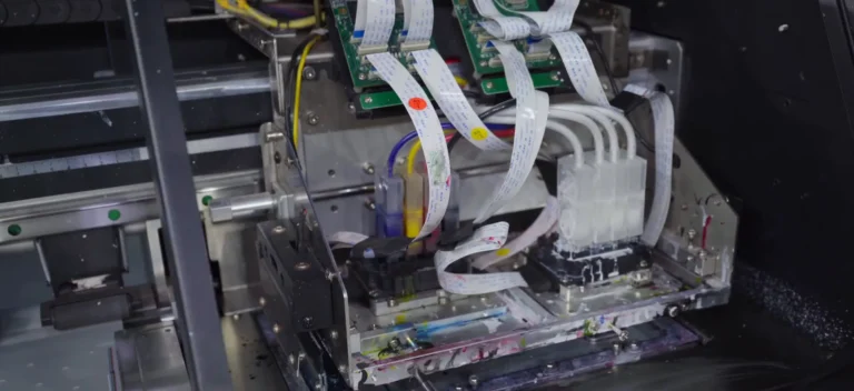
Replace the printhead, restore its cable and damper connections, and fit the matching decoder SD card. Complete mechanical alignment and software calibration before checking the finished print.
Applicable model: General. Required items: Screwdrivers, replacement printhead with its matching decoder SD card, dust-free cloth, and a computer with the printer control software.
Step 1. Prepare the Printer and Remove Covers
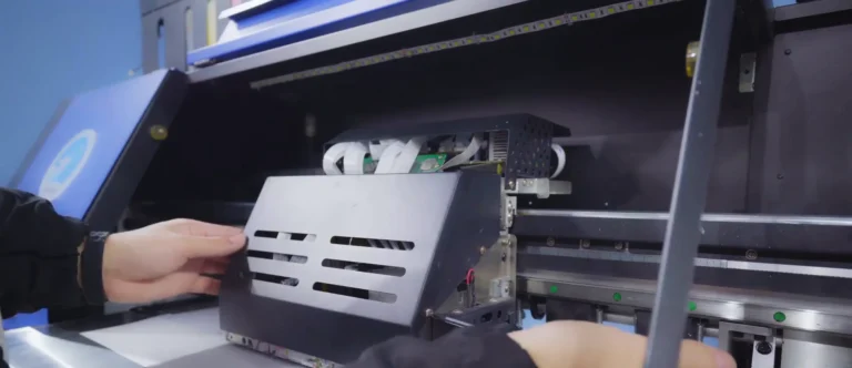
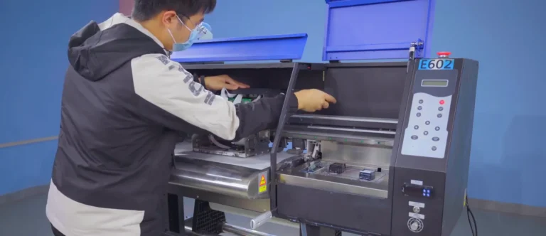
1.1 With the printer switched off and unplugged, remove the carriage cover and the headboard cover to expose the printhead assembly (See Figure 1.1).
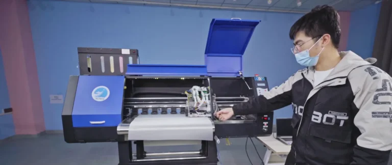
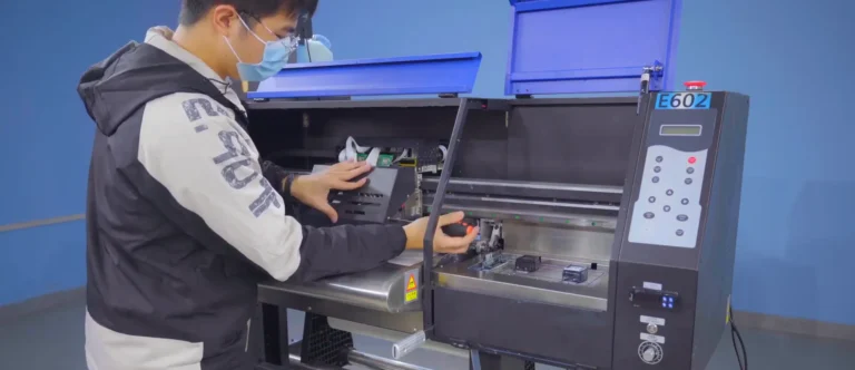
1.2 Switch on the printer briefly to let the carriage return to its home position and cap the printhead. Then switch off and unplug the printer before handling the dampers, cables, or printhead (See Figure 1.2).
Step 2. Remove and Replace the Printhead
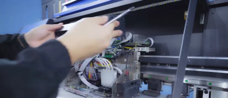
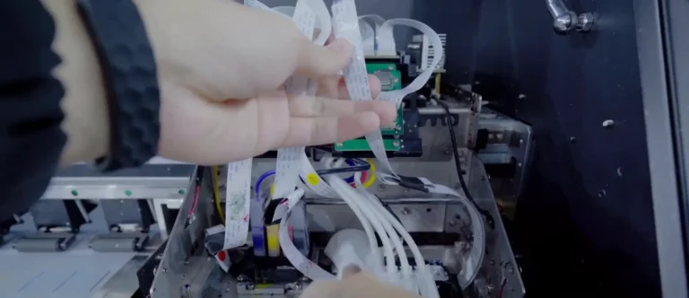
2.1 Place dust-free cloth on both sides of the printhead to catch ink released while removing the dampers (See Figure 2.1, left).
2.2 Carefully lift the dampers off the printhead, keeping their ink tubes connected.
2.3 Disconnect the printhead ribbon cables. Keep their labels visible so each cable can be returned to its matching connection (See Figure 2.1, right).
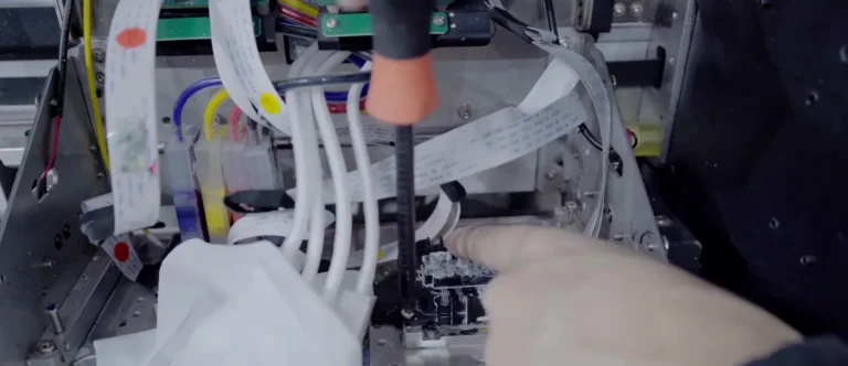
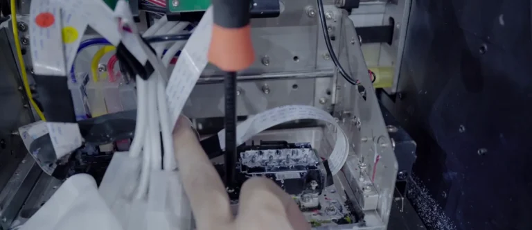
2.4 Remove the printhead fixing screws and lift out the old printhead (See Figure 2.2, left).
2.5 Place the replacement printhead in the same mounting position and reinstall its fixing screws (See Figure 2.2, right).
Step 3. Restore Connections and Match the Decoder
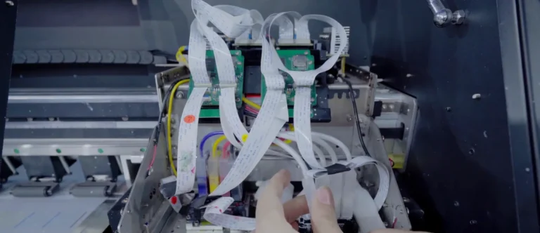
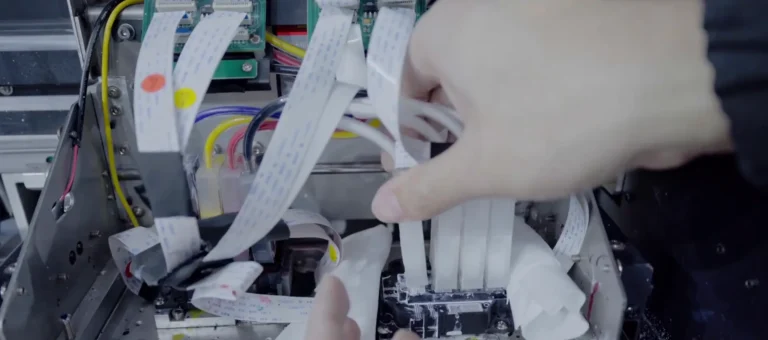
3.1 Reconnect the ribbon cables according to their labels, matching each cable to its original connector (See Figure 3.1, left).
3.2 Keep dust-free cloth around the printhead while refitting the dampers. Seat each damper in its original position, then check that the cables are properly connected (See Figure 3.1, right).
3.3 Fit the decoder SD card supplied for the replacement printhead into the corresponding decoder card slot (See Figure 3.2).
3.4 Remove the protective cloth and check the connections before switching on the printer.
3.5 Check the decoder indicators after startup without touching the powered circuit boards. For the illustrated decoder, two steadily lit indicators indicate normal operation.
Step 4. Adjust the Printhead Vertical Alignment
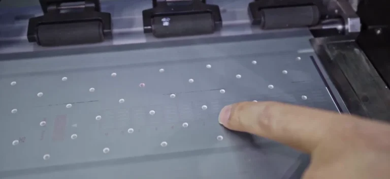
4.1 Print the vertical alignment test pattern and inspect the printed lines for tilt or deviation (See Figure 4.1).
4.2 Switch off the printer and loosen the four printhead fixing screws (See Figure 4.2, left).
4.3 Turn the adjustment screw left or right according to the deviation in the test pattern to correct the printhead alignment (See Figure 4.2, right).
4.4 Switch on the printer and print the test again. Once the alignment is satisfactory, switch off the printer and tighten the fixing screws. Power on again for the software calibration.
Step 5. Calibrate Fine Alignment and Feed Step
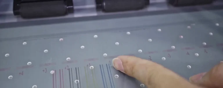
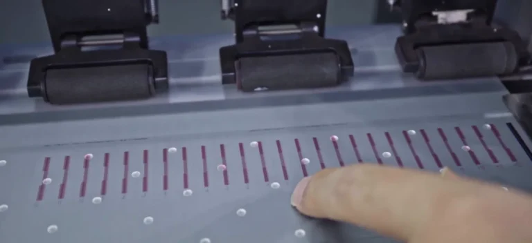
5.1 Inspect the fine adjustment pattern and find the numbered position with the straightest alignment. Add its signed correction to the corresponding current calibration value in the printer control software (See Figure 5.1).
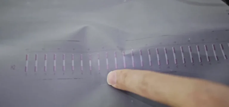
5.2 Print the base step calibration pattern. Select the numbered position with the least deviation and enter the resulting correction in the step calibration setting (See Figure 5.2).
5.3 Use the result from the current test pattern for each correction. Print the relevant pattern again to check the adjustment.
Step 6. Calibrate the Head Spacing
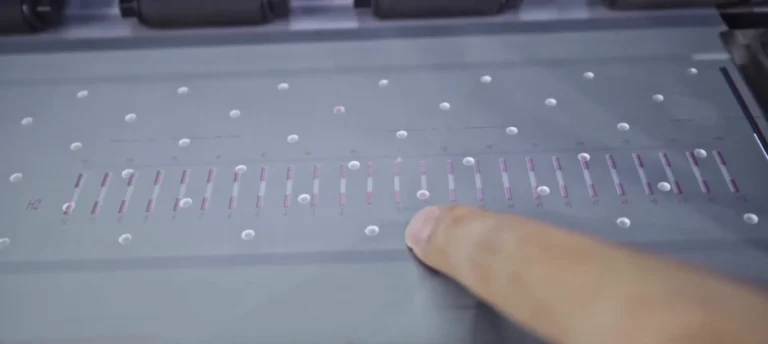
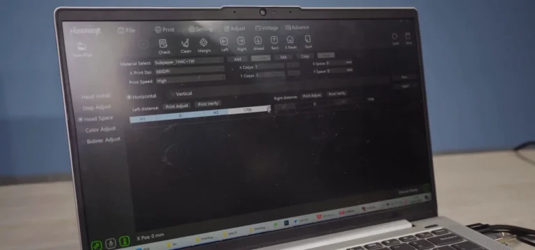
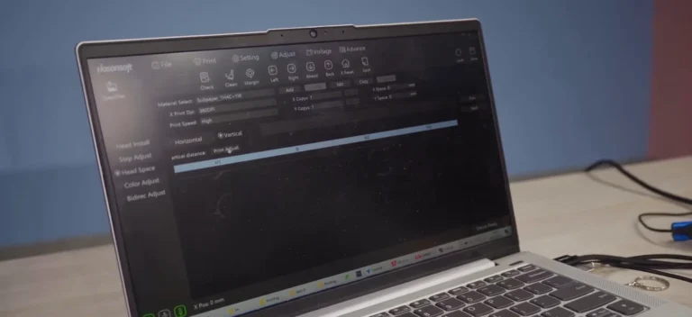
6.1 In Head Space, select Horizontal and print the spacing calibration pattern. Find the numbered marks with the closest alignment (See Figure 6.1, left).
6.2 Calibrate both the left and right travel directions, entering each result in its corresponding Left distance or Right distance setting (See Figure 6.1, right).
6.3 Select Vertical in Head Space and print its calibration pattern. Read the best aligned position and enter the corresponding vertical spacing correction (See Figure 6.2).
6.4 Print the spacing patterns again and confirm that the alignment has improved before proceeding.
Step 7. Calibrate Bidirectional Printing and Save
7.1 Print the bidirectional calibration pattern. Find the numbered position where the paired marks overlap most closely, then enter the correction under Bidirec Adjust (See Figure 7.1, left).
7.2 Save the calibration data in the printer control software (See Figure 7.1, right).
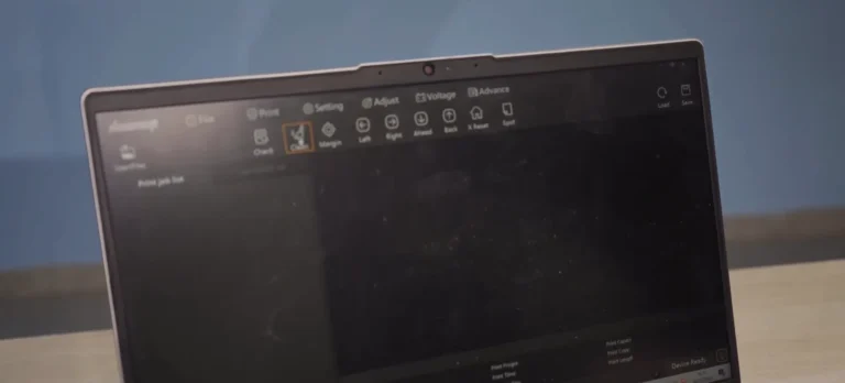
7.3 Print a nozzle check strip to confirm that the printhead is printing normally after replacement and calibration (See Figure 7.2).
Step 8. Refit the Covers and Check the Finished Print
8.1 Switch off and unplug the printer before refitting the covers.
8.2 Reinstall and secure the headboard cover, then reinstall and secure the carriage cover (See Figure 8.1).
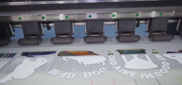
8.3 Switch on the printer and print a sample image (See Figure 8.2).
8.4 Inspect the sample for missing lines and visible alignment errors before returning the printer to regular use.