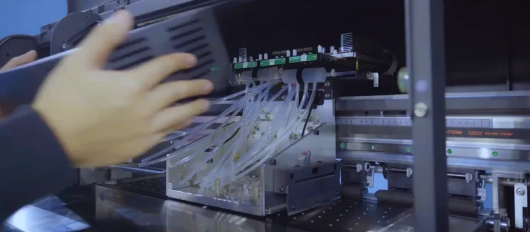
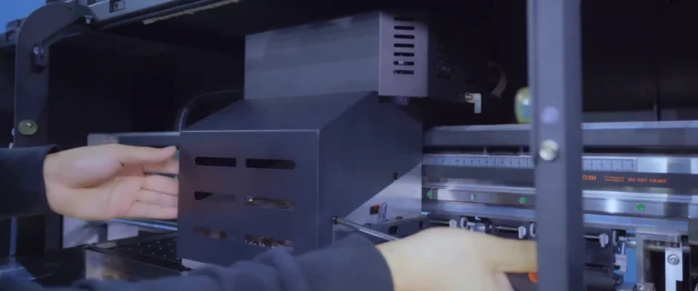
Replace the encoder strip while preserving its end fixtures, spring attachment, and path through the encoder reader. Keep the two middle screws of the protection channel in place when removing its covers.
Applicable model: General. Required items: compatible encoder strip, screwdriver, pointed tool for the end fixing holes, a small piece of printing film, and the original strip fixtures.
Step 1. Position the Carriage and Remove the Protection Covers
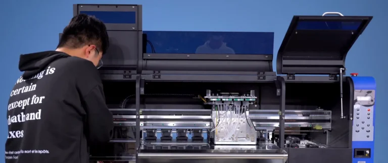
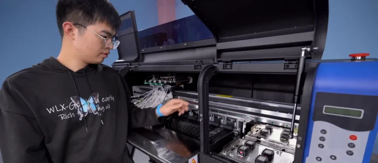
1.1 Open the service covers. Press the Left control to move the carriage toward the center, then switch off the printer before working on the strip (See Figure 1.1).
1.2 Expose the strip protection channel. Remove the screws securing its removable covers on both sides. Do not loosen the two middle screws (See Figure 1.2, left).
1.3 Lift off the protection covers and retain them with their screws for reinstallation. Remove the carriage housing and headboard cover as needed for access to the reader (See Figure 1.2, right).
Step 2. Remove the Old Strip and Retain Its Fixtures
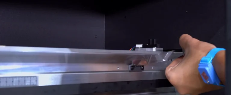
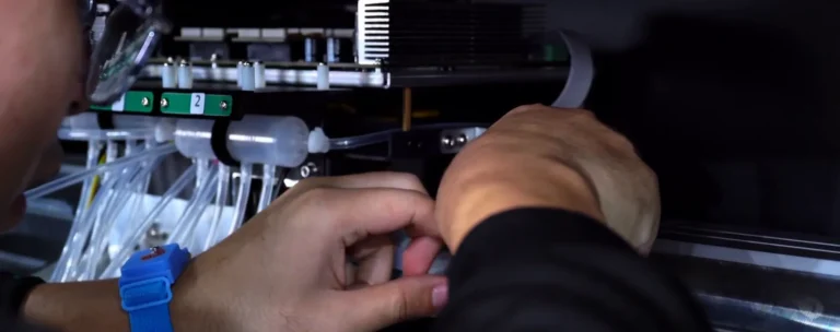
2.1 Release the old strip from its end attachments and spring hook, then carefully withdraw it from the channel and the encoder reader. Keep its orientation as a reference for the replacement (See Figure 2.1).
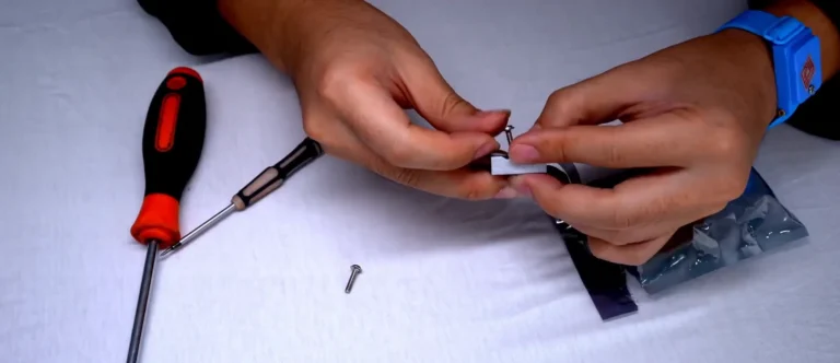
2.2 Remove the fixtures from both ends of the old strip. Keep the plates, screws, and spring attachment in their original arrangement for reuse (See Figure 2.2).
Step 3. Prepare and Route the New Strip
3.1 Transfer the original fixture to the corresponding end of the new strip. Match the strip orientation and plate arrangement to the old strip (See Figure 3.1, left).
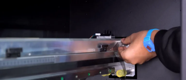
3.2 Install this end attachment in its original position and feed the strip across the carriage travel area (See Figure 3.1, right).
3.3 Place the new strip in the middle groove of the protection channel. A small piece of printing film can help guide it into the groove without twisting it (See Figure 3.2).
Step 4. Secure the Spring End and Align the Reader
4.1 Use the original end fixture as a guide to make the two fixing holes required at the opposite strip end. Fit and secure the original plates in the same arrangement (See Figure 4.1, left).
4.2 Attach the completed end fixture to the original spring hook (See Figure 4.1, right).
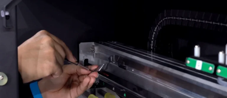
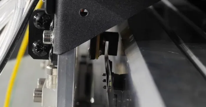
4.3 Ensure that the new strip passes through the central groove of the encoder reader. If the reader was loosened for access, refit it in its original position and reconnect its wire (See Figure 4.2).
Step 5. Refit the Protection Covers and Check the Strip Path
5.1 Recheck that the strip sits in the middle channel groove and passes through the encoder reader without twisting (See Figure 5.1, left).
5.2 Return the protection covers to their original positions and tighten their fixing screws (See Figure 5.1, right).
5.3 With the printer still switched off, gently move the carriage along the rail and observe the strip. Check that the carriage travels without pulling the strip out of its groove or reader slot (See Figure 5.2).
Step 6. Reinstall the Covers and Return Home
6.1 Reinstall the headboard cover and carriage housing, then secure their original fixing screws (See Figure 6.1).
6.2 Once the covers are secure, switch on the printer and use its controls to return the carriage to its starting position. Switch off the printer after the carriage has returned and stopped (See Figure 6.2).