
Replace Capping Station Motor and Screw Rod
Select Your Printer Model
(Default: Universal)
Choose your model from the drop-down menu below.
XINFLYING Replace Capping Station Motor and Screw Rod
Applicable Model: Universal
Video Tutorial
Replace the capping station motor, service the screw rod and its central fixture, and restore the station covers. Preserve the original motor wiring and cap plate position.
Applicable model: General. Required items: compatible replacement motor and central fixture, matching screw rod if replacement is required, screwdrivers, and a container for the screws.
Step 1. Open the Capping Station
1.1 Position the carriage clear of the capping station, then switch off and unplug the printer. Remove the outer station cover without dropping screws into the mechanism (See Figure 1.1, left).
1.2 Remove the four screws securing the cap top plate. Lift the plate aside while supporting the connected tubes (See Figure 1.1, right).

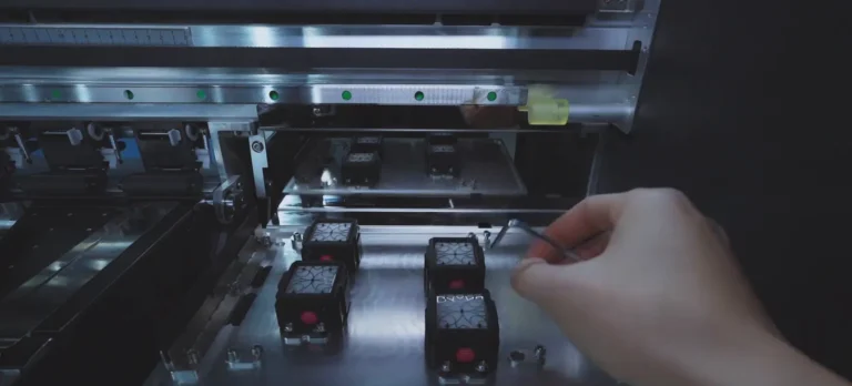
1.3 Remove the four internal cover screws. Take the green buffer rubber off the guide rod and lift out the internal cover (See Figure 1.2).


Step 2. Remove the Motor Assembly
2.1 Remove the motor assembly mounting screws. Loosen the set screws on the gold coupling that connects the motor shaft to the screw rod (See Figure 2.1).
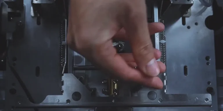

2.2 Open the side electrical compartment and its wire duct cover. Trace the motor lead, record its plug position, and disconnect it. Lift out the motor assembly (See Figure 2.2, left).
2.3 Remove the coupling from the motor shaft. Remove the four bracket screws and separate the old motor from its bracket (See Figure 2.2, right).


Step 3. Install the Replacement Motor
3.1 Fit the new motor into the original bracket in the same orientation. Tighten the four bracket screws (See Figure 3.1, left).
3.2 Refit the coupling onto the motor shaft and secure its two set screws (See Figure 3.1, right).

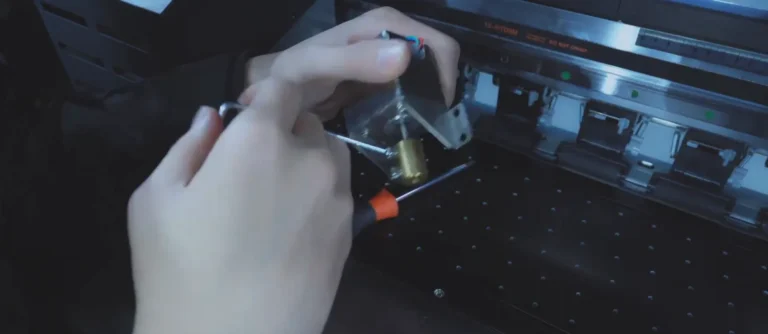
3.3 Return the motor assembly to the capping station. Align the coupling with the screw rod without forcing the parts together, then secure the motor mounting screws (See Figure 3.2).


Step 4. Service the Screw Rod and Central Fixture
4.1 Loosen the coupling set screws on the screw rod side. Rotate and withdraw the screw rod from the mechanism (See Figure 4.1, left).
4.2 Remove the central fixture and fit the compatible replacement fixture in the same position (See Figure 4.1, right).
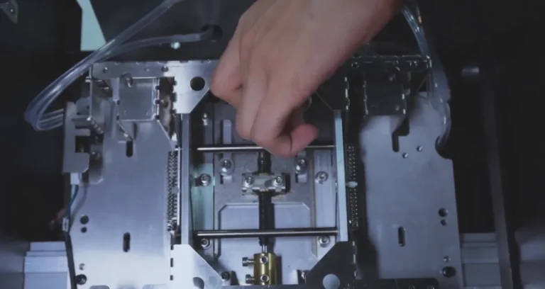

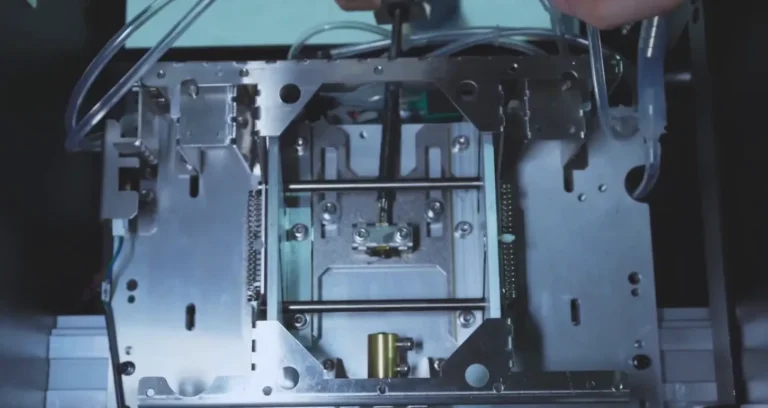
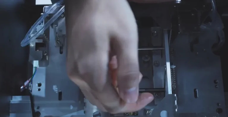
4.3 Thread the screw rod back through the new fixture. If the rod itself requires replacement, use a matching compatible rod in the same assembly position (See Figure 4.2, left).
4.4 Align the screw rod with the coupling and tighten the coupling set screws securely (See Figure 4.2, right).
Step 5. Reconnect the Motor and Internal Cover
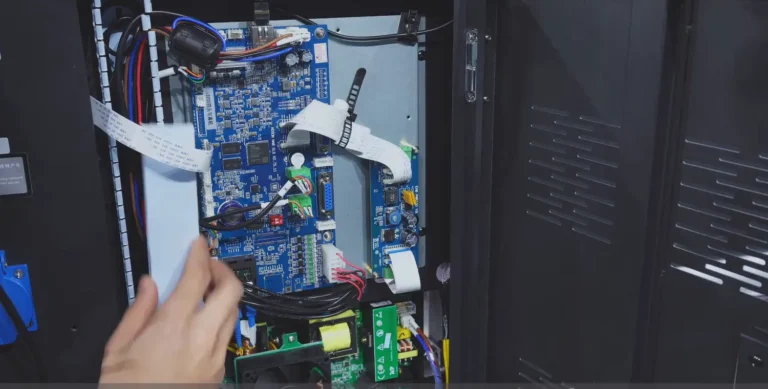
5.1 Route the motor lead back through the wire duct and reconnect it to the recorded socket. Refit the wire duct cover and close the electrical compartment (See Figure 5.1, left).
5.2 Check that no loose screws, tools, wires, or tubes obstruct the moving mechanism.
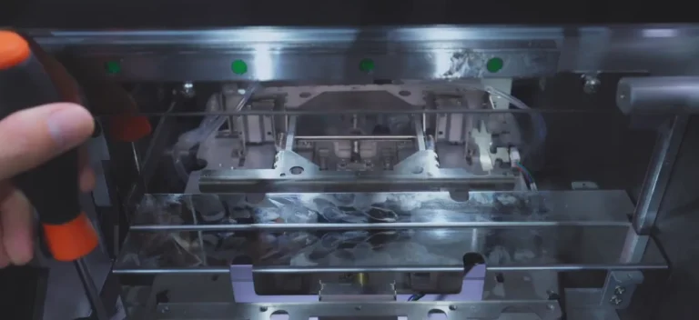
5.3 Refit the internal protective cover and its four screws. Restore the green buffer rubber on the guide rod (See Figure 5.1, right).
Step 6. Restore the Cap Plate and Home the Carriage
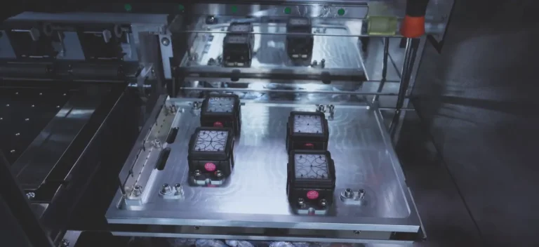
6.1 Lower the cap top plate into its original position and align the four mounting holes. Keep its tubes clear of the moving parts (See Figure 6.1, left).
6.2 For the illustrated station, position the plate toward the lower left corner before tightening its four mounting screws (See Figure 6.1, right).
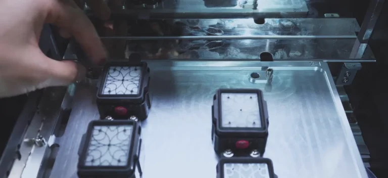

6.3 Refit the outer station cover and tighten its screws (See Figure 6.2, left).
6.4 Clear the work area and power on the printer. Allow the carriage to return to its home position, then switch off the printer (See Figure 6.2, right).

If you are not sure about any step, please contact the XINFLYING Technical Support Team for assistance.
© 2026 XINFLYING Technical Team. All rights reserved.
Do not reproduce or modify this document without permission.
For support, please contact: [email protected] | www.xin-flying.com