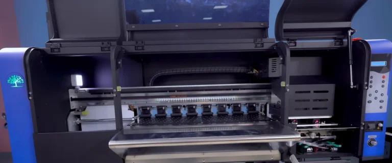
Adjust Printhead Height and Parallelism

Select Your Printer Model
(Default: Universal)
Choose your model from the drop-down menu below.

XINFLYING Adjust Printhead Height and Parallelism

Applicable Model: Universal

Video Tutorial

Adjust the T604 carriage height by releasing the fixing screws, turning the upper adjustment screws, and securing the carriage before refitting its covers.

Required tools: Phillips screwdriver and a matching hex key.

Step 1. Prepare the Carriage and Remove Covers

1.1 Press the Left button to move the carriage to the center, then switch off the printer before removing the covers (See Figure 1.1).

Figure 1.1. Position the carriage at the center before switching off the power.

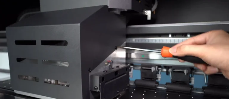
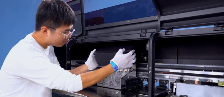
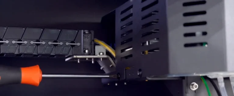
1.2 Loosen the four screws around the carriage cover and remove the cover (See Figure 1.2, left).
1.3 Loosen the four screws on the headboard cover and remove it to expose the carriage adjustment area (See Figure 1.2, right).

Figure 1.2. Remove the carriage cover
Figure 1.2. headboard cover

Step 2. Release the Carriage Fixing Screws

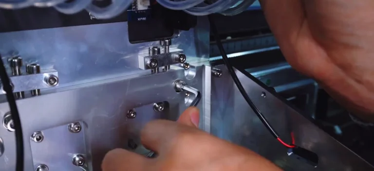
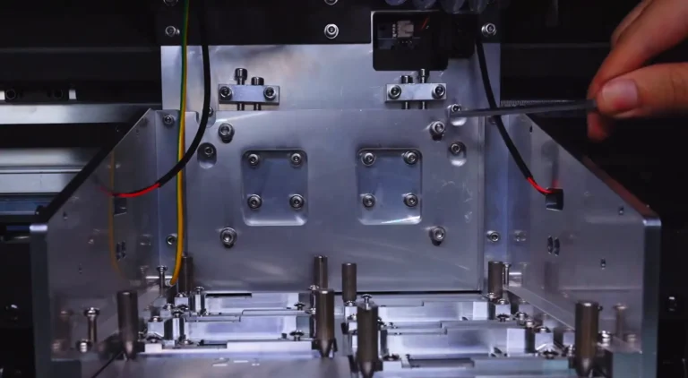
2.1 Loosen the four large fixing screws at the outer corners of the vertical carriage plate. Leave these screws in place (See Figure 2.1).

Figure 2.1. The upper-right outer fixing screw on the carriage plate.

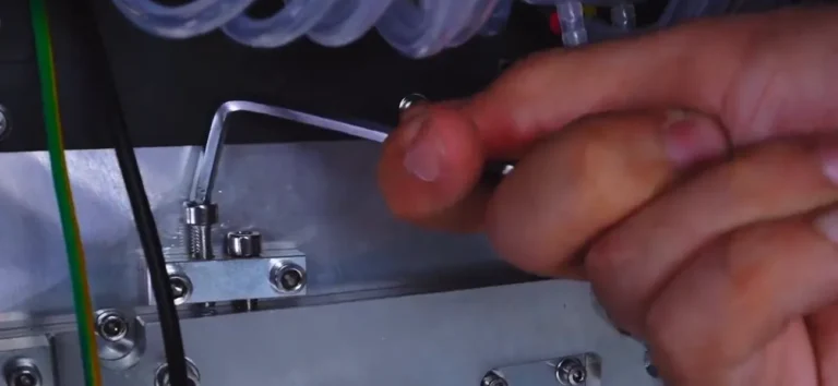
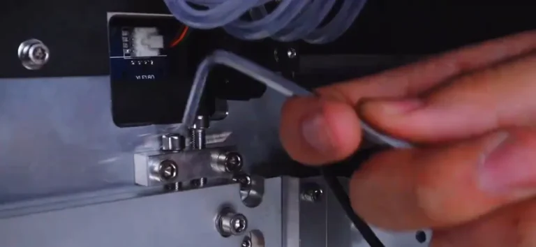
2.2 Loosen the two shorter upper screws, one on each top adjustment block. These sit beside the taller height adjustment screws (See Figure 2.2).

Figure 2.2. Locate the shorter upper screw beside the taller adjustment screw.

Step 3. Adjust the Carriage Height

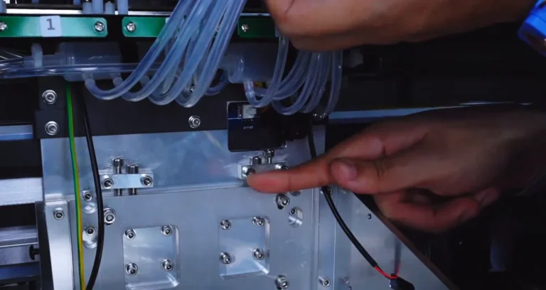
3.1 Use the hex key to turn the taller vertical height adjustment screw on each upper block to raise or lower the carriage (See Figure 3.1).
3.2 Adjust both sides gradually to keep the carriage level. Check the clearance beneath the carriage before securing its position.

Figure 3.1 (left). Adjust the left side of the carriage.
Figure 3.1 (right). Adjust the right side of the carriage.

Step 4. Secure the Adjusted Position

4.1 Tighten the four large outer fixing screws on the carriage plate to lock the adjusted position (See Figure 4.1, left).
4.2 Lightly tighten the four screws on the two upper blocks by hand until they no longer move (See Figure 4.1, right).

Figure 4.1 (left). Secure the carriage plate.
Figure 4.1 (right). Secure the upper block screws.

Step 5. Refit the Covers and Return the Carriage

5.1 Reinstall the headboard cover and tighten its four screws (See Figure 5.1, left).
5.2 Reinstall the carriage cover and tighten its four screws (See Figure 5.1, right).

Figure 5.1 (left). Refit the headboard cover.
Figure 5.1 (right). Refit the carriage cover.

5.3 Switch on the printer, return the carriage to its starting position, and then switch the printer off (See Figure 5.2).

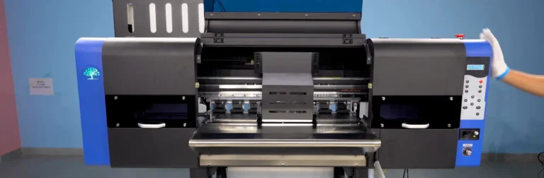
Figure 5.2. Return the covered carriage to its starting position before shutdown.

If you are not sure about any step, please contact the XINFLYING Technical Support Team for assistance.

© 2026 XINFLYING Technical Team. All rights reserved.
Do not reproduce or modify this document without permission.
For support, please contact: [email protected] | www.xin-flying.com

Request an Equipment Quote

Tell us your equipment and production needs. Our team will recommend a suitable machine and provide a tailored quotation.