
Install Decoder Card
Select Your Printer Model
(Default: Universal)
Choose your model from the drop-down menu below.
XINFLYING Install Decoder Card
Applicable Model: Universal
Video Tutorial
Mount the decoder card on the carriage and connect the labeled ribbon cables between the card, headboard, and printheads. Keep the SD card side and each cable contact face correctly oriented.
Applicable model: General. Required items: compatible decoder card, screwdriver, and antistatic protection.
Step 1. Open the Covers and Prepare the Card
1.1 Switch off and disconnect the printer. Remove the carriage housing fixing screws and lift off the housing. Remove the upper headboard cover as well (See Figure 1.1).
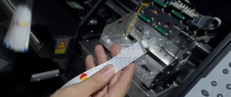

1.2 Identify the wide and narrow ribbon cables before connecting them. Preserve their labels and avoid creasing the cables (See Figure 1.2, left).
1.3 Remove the protective plastic films from the decoder card before installation (See Figure 1.2, right).
Step 2. Mount the Decoder Card
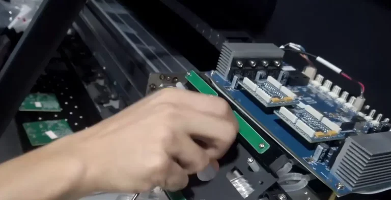
2.1 Locate the decoder card mounting position next to the headboard. Remove the screws from this mounting position and retain them (See Figure 2.1, left).
2.2 Place the card on its mount with the SD card side facing up. In the illustrated mounting orientation, the SD card slot is at the upper right corner (See Figure 2.1, right).
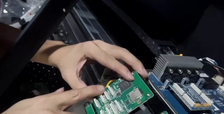
2.3 Align the mounting holes and tighten the retained screws to secure the card (See Figure 2.2).
Step 3. Connect and Check the Ribbon Cables
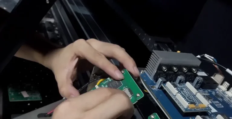
3.1 Connect the decoder card ribbon cables to the headboard first. Match the cable labels to the letter markings beside the decoder card sockets (See Figure 3.1, left).
3.2 Connect the remaining labeled cables to their matching sockets. Use the labels to identify each connection rather than cable width alone (See Figure 3.1, right).
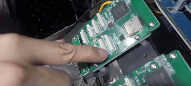
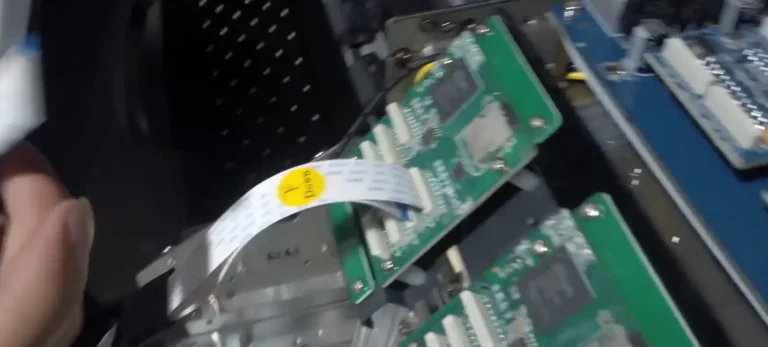
3.3 For a wide ribbon cable, align the exposed metal contacts with the contact pins inside the socket. Insert the cable straight and fully without tilting it (See Figure 3.2, left).
3.4 Check all cable ends for full seating, correct orientation, and damage. Do not fold the ribbon cables sharply or leave them twisted (See Figure 3.2, right).
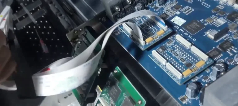

3.5 Keep power disconnected while refitting the removed covers. Ensure that the covers do not pinch any ribbon cables.
If you are not sure about any step, please contact the XINFLYING Technical Support Team for assistance.
© 2026 XINFLYING Technical Team. All rights reserved.
Do not reproduce or modify this document without permission.
For support, please contact: [email protected] | www.xin-flying.com